|
Celebrating 33 years providing high quality products and advice.
|
| Our Local Time Is 4:49:12 PM. |
| Call us at 818-786-0600. We are here to help! |
 |
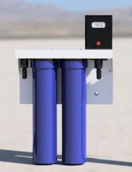
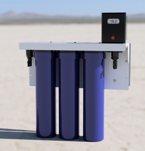
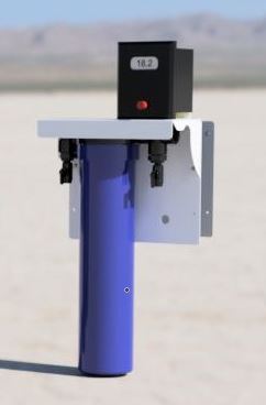
ON SALE NOW
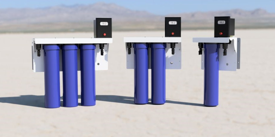
Introducing the Polaris Lab Water Systems
High Purity Water Made In The USA.
Click here for more info. |
How To Install A Water Softener
Select Best Softener
Softener Selection Calculator
Softener Capacity Calculator
Media Cylinder Calculator
click to enlarge
Note:
If you have an electric water heater, we recommend that you turn off the electricity to the water heater while installing the softener. Once you are satisfied with the installation, turn on a few hot and cold water faucets and let them run. When certain there is no more air in the pipes, then turn on electricity to the water heater.
Step 1:
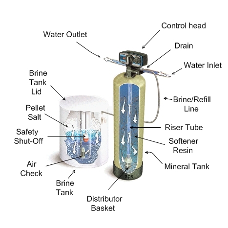
Location of softener is important. It should dry, protected, level, and non-freezing area (34- 120 deg. F) The tanks should be set close to each other. The tank with the removable lid is the brine tank (for softener salt or potassium chloride) and is the tank you need to refill occasionally, so make it the more accessible of the two. Do not put salt in the brine tank until you have put the softener into service and have tested the cycles.
Step 2:
You will need a standard outlet that is not controlled by a switch, which can be 50 feet from the softener.
Step 3:
You will need a drain for the backwashing cycles. This should be no longer than 20 feet from the softener. You will need to purchase a flexible 1/2” I.D. vinyl or polyethylene line. This backwashing drain line will be under pressure when backwash cycle is on. Make sure drain line is secured. The drain line will need to run into a drain, which should be a min. 1 1/2“ size, and ideally be below the top of the head of your softener. Local codes should be adhered to.
Note: Never connect the drain line directly into a drain. Allow an air gap between the drain line and waste line to prevent possibility of back-siphoning.
Step 4:
Once you have determined the exact location of your softener, it is time to fill the mineral/media tank (taller of 2) with the cation resin beads.
The distributor tube should be in the mineral tank with screen intake at the bottom, open end at top. The open end should be trimmed to be flush with the top of mineral tank. The screen intake should be resting centered on the bottom.
There should be a plug in the open end of the distributor tube. This is to keep any media from falling into the tube while loading the mineral tank.
Place the provided funnel into the mineral tank and begin to put media into the mineral tank. Be careful to keep the distributor tube centered as best you can while filling. There should only be enough media to fill the tank ½ to 2/3 full. The mineral tank should not be filled to the top. It is necessary for the media to have room to move during the backwash cycle. An easier, but slower, way to fill the mineral tank is to use a small scoop to pour the media into the funnel.
Once filling of the mineral tank is completed, carefully remove the plug from the distributor tube. Do not pull upwards on the distributor tube.
The control valve (head) now must be screwed onto the mineral tank. Be sure the large O-ring is in place. As you screw the control valve on, make sure the hole in the center of the valve fits over the distributor tube. No pipe dope should be used on the threads. The control valve should be hand tightened snugly clockwise.
Step 5:
You are now ready to install the bypass valve (if applicable) to the control valve. The in and out arrows on the bypass valve should be pointing the same directions as the control valve arrows. Affix the yoke to the bypass valve.
Step 6:
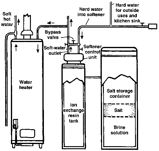
Water connections to and from softener will now be connected to the bypass/yoke. Typical male pipe thread connection is ¾” but may be larger if ordered as such. Take care if sweating copper not to melt the plastic connection. We recommend type L copper pipe over type M as type L is thicker.
Step 7:
Between the two tanks you will need to connect the supplied 3/8” O.D. tubing. One end connects at the brass tube fitting on the control valve and the other end connects to the elbow fitting inside the brine tank.
Step 8:
You can now connect the brine tank overflow. Connect ½” tubing from the brine tank drain elbow to a drain. This drain line will not be under pressure. DO NOT tie into the backwash drain line. This line should be higher than your drain line.
Now follow the instructions in the control valve manual for putting the softener into service.
Remember to check with local code officials and install per code.
|
Images are representative of the products. Images may or may not be of the actual product. If it is important e-mail us for an actual image if available.
* Flat Rate UPS shipping when able to ship via UPS and is in the USA excluding Hawaii and Alaska.
Larger Items may not be able to ship via UPS, in that case freight charges will be quoted seperately.
International shipping will be quoted after the order is placed. You will have the opportunity to cancel before we finalize your order.
Terms and conditions
Credit Application
Privacy
Policy
List All Products
|